Saturday, April 24, 2010

What I've been doing

After finally obtaining some basic components (salvaging them, rather) I finally cobbled together a joule thief. I give credit and mad props to evilmadscientist.com for helping me out with this one. Yay! Well that was a good half-hour project.


Anyway, on to bigger and better things. I've finally started/completed (somewhat) work on an 8x8 LED matrix. Everything is all soldered up and running fine; the only thing left is to refine the code for it. Pictures and video are listed below. It's run off three pins from the arduino duemilanove, controlling two 74HC595 shift registers. The code work is a modified code from the ASK manual by earthshine design. Improvements for next time: hook the anodes up to either a transistor or a P-FET, and ground to a darlington array. And make it bigger. Oh and use diffused LEDs (I had clear ones so I decided to use wax paper over the array to diffuse the light a little and make the image clearer).


Oh and finally, one last thing, remember that welder i made and posted about? Well it's all finished now and it looks pretty dang good.


Saturday, November 28, 2009

Home Made Welder


Another instructable I followed--but this one's not quite done yet.

http://www.instructables.com/id/Build-a-Microwave-Transformer-Homemade-Welder/

I built the welder, sure, and it works fine, but the problem is that I just don't have a good enough case to carry it around in. Right now, the components are all loose and wiggle around, and I have to carry the welder around on a piece of plywood if I want to use it. Either way, it was a neat build and it works great. Fun stuff.

Saturday, July 4, 2009

LED Glow Cube

Inspired by this instructable: http://www.instructables.com/id/Awesome-led-cube/

Now, i made mine a tad bigger than what was presented, threw in more LEDs and a 9V, and ran into a problem filling it with hot glue. hot glue guns are incapable of handling such a large volume, so i cut open a pop can, and melted the sticks in that, then poured it in the cube (while being careful not to encase the switch as well). From there, I put on metallic tape that my dad had sitting around, and cut out the patterns with an x-acto knife and removed the excess tape. The result is this:

Wednesday, May 20, 2009

Light Writer

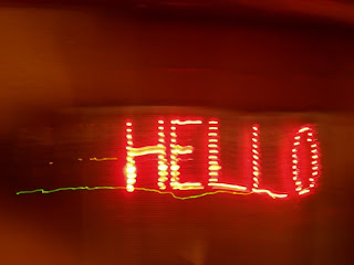
Okay, new project time! It's called Light Writer... and it... writes--with light. This ones kind of like POV projects, but slower.

Above is a picture of what it ultimately is capable of.

As the camera takes a long exposure picture, the LEDs blink in sequence to spell out words
In this case, it was still on the breadboard and I moved the camera--not so good.
This is the final case, seen from the top
This is what the case looks like looking at the front
The back of the case. The nuts unscrew to remove the arduino, and there's a power switch that I have to find a home for as well. (I also still have to epoxy the bolts in place)
early breadboarding
Hooray! (again, moving the camera...)

*I modified the example code from the playground to suit my needs (twelve LEDs instead of 5)

Saturday, May 2, 2009

1525 Belt Buckle--Unfinished


I've been trying to make a belt buckle for a while now for my FIRST robotics team (FRC, 1525 if that matters). We have a plasma cutter at our school, so i drew up the buckle in AutoCAD. From there it went into flashcutCNC, and from there the drawing was cut out by the plasma cutter. I had two failed attempts--one was the machine's fault (the torch moved but would not cut... it was strange) and the other was my fault (line underneath a line that i didn't notice, so it cut out that part twice and that resulted in one of the sides being too thin). But here it is now. I plan on lopping off the part for the buckle and the pin and welding them on, but for now, this will do fine. The black sharpie marks will be dremel'd out and leave a little depression where they are to pronounce the numbers better. The only problem is that it cracked where the buckle loop is, so that will have to be welded that back together.

Sunday, April 26, 2009

Daft Punk Helmet

My friend told me about the group "Daft Punk" about two months ago--I checked out their music, then saw heard about their helmets. As soon as i saw one, I was immediately attracted to it and it became my goal to make one. Originally, I wanted to have an LED matrix on it that could spell out words, but, in the interest of time (I needed it for a costume party), I had to cut it short to a "knight-rider"-esque display. There's a video below (mind the parents talking...) as well as details as to how it was made. I gave myself a $100 budget for the entire project (would've been a lot cheaper had I already owned an I/O board). I was just overbudget for the whole project by $1.61.


How it was made:


first step. cut out styrofoam blocks. i sketched up a CAD drawing to find proper dimensions then cut them out. I got the foam sheeting at a Home Depot.


This is how they eventually go together.


First Shipment of electronics stuff arrived; LEDs with free resistors for 12V, shame, i could've used 5V... I got these off eBay for $6.99 from china.
This is what the blocks looked like all glued together. I used Gorilla Glue, and it worked nicely.
Second and third shipment of electronics! woo hoo! the second to come in were 4794 LED driver chips and 150 Ohm resistors. A day later came the arduino duemilanove (http://arduino.cc/en/Main/ArduinoBoardDuemilanove) microcontroller board and the breadboard. I threw together this circuit (http://www.arduino.cc/en/Tutorial/KnightRider) to make sure it all works. I got the breadboard and the duemilanove from sparkfun (http://sparkfun.com). I got the 4794 chips (that i ended up not using because of time constraints) and the resistors from mouser electronics (http://www.mouser.com).
I used a sander and a saw to trim down the block and shape it as such; i know its a bit different than that of the actual daft punk helmets but, oh well.
Again, just a picture of it shaped.
I had yet to cut out the place for the visor at that point.
I put fiberglass sheeting and resin on the foam to give it some strength...
..but the resin ate away at the foam and there were gaps left between foam and fiberglass.

My dad suggested magnet wire for the leads going to the LEDs, we had some lying around, so... (but in reality, these proved frail and difficult to solder.)

Time to heat form acrylic! I read that you could shape acrylic after heating it in an electric oven.
It worked well. We ended up using a toaster oven at 275 degrees.

This is the visor finished after heat forming. I drew it up in CAD beforehand, with the holes plotted out. The label on the acrylic sheet said, "Easy to Cut." Yeah, right. It took a while to figure out how to cut it without it snapping, but eventually i found out that a dremel tool with something that acted as a mill bit would work perfectly. I had printed out the CAD drawing for the holes, and taped that to the piece
Time to sand fiberglass; i had to wear a respirator.

As I said, the fiberglass left gaps, so we filled that with Bondo.
And, with some paint, the visor went in with the electronics and, voila! my own daft punk helmet.

Here's the helmet up close with the electronics box. The paint was only shiny in some places--i think i might have to redo that and put more Bondo on and make it perfect.
Here's the electronics box--I cut out some acrylic, drilled holes, and soldered the wiring to the resistors, and then put the wires in the corresponding pins. Underneath that is the brain of the organization--the Arduino Duemilanove. At the bottom of the tin is the 9V battery that powers it all.
The box was the perfect size for it all--everything fit snugly--but not too snug. This ends up going in one of the pockets of the $3 thrift shop three-piece suit on which i wrote daft punk on the back.